Resources
 Part of the Oxford Instruments Group
Expand
Collapse
Part of the Oxford Instruments Group
Selecting a Camera window to optimise Transmission Efficiency
The camera window plays an important role in the overall transmission efficiency of the detection system. The camera manufacturer will therefore select a standard camera window that provides a transmission efficiency profile that matches that of the camera sensor, and typical applications. There may be some applications that an alternative camera window may be more suited to specific experimental needs. Generally, when specifying a camera window one wants to maximise the transmission within the desired wavelength region. Use of anti-reflection (AR) coatings on both surfaces of the window can minimise reflection losses at each surface leading to enhanced transmission compared with the bare uncoated substrate. However, there is often a trade-off between the best possible transmission for a specific wavelength region and having good efficiency over a wide wavelength range (Broadband). Hence there are cases where the uncoated substrate may be a better option, particularly if one wants to maintain good transmission from the UV right up to the SWIR region.
Minimising Fringing Effects at Higher Wavelengths
Another key consideration for some applications is to minimize “fringing” effects due to the window; this effect is directly related to the coherence of the light incident on the camera. Fringing effects can occur due to the etaloning effect within the window substrate. Fringing can appear as faint lines or banding superimposed on the image or spectrum. This undesirable optical effect is due to constructive/destructive interference and can occur with coherent light sources, particularly at wavelengths above ~700 nm. An effective way of reducing fringing is by using what is called a “wedged window”. The wedged window is fractionally thinner at one side than the other so that it has a 0.5-1.0 degree angle across the face of the window. This helps break up the coherence of the interfering light waves and thus reduces the fringing effect that may otherwise occur with a unwedged normal camera window.
The following considerations are taken into account when deciding what window to use:
Camera Window Materials and their Properties
There are two materials selected for use in the windows of Andor cameras. These are: UV Grade Fused Silica and Magnesium Fluoride.
UV Grade Fused Silica (FS): UV grade fused silica is formed from silicon dioxide. It is a synthetic non-crystalline amorphous material which offers good transmittance in the NIR, visible and UV regions down to 180 nm. Whilst similar to quartz which is also composed of silicon dioxide, their structure and optical performance are significantly different. UV Grade fused Silica has a higher homogeneity and transmittance than Quartz. Fused silica has a higher damage threshold and is often used when working with high power lasers. It can also offer good transmission up into the IR region to beyond 2 μm.
Magnesium Fluoride (MgF2): MgF2 offers both good and broad transmission into the deep UV or VUV region and up into the SWIR region. It is most commonly used for UV optics and can transmit down to below 120 nm. However, MgF2 is slightly birefringent, so windows are normally manufactured so that the c-axis is parallel to the optical axis of the system and therefore perpendicular to the plane of the window. MgF2 can also transmit up to beyond 7 μm in the IR region so is often the window of choice for experiments within the SWIR region. VUV grade material is used for the Andor camera windows. This has a low refractive index and has a high transmission over the whole spectral range even without the use of AR coatings; the addition of an AR coating whilst possible offers little improvement to this already high transmission. MgF2 is more expensive than fused silica.
AR coatings and optimized transmission curves for different λ regions
Window transmission curves are available to view in our Camera Windows Selector Tool. This enables the overall transmission to be compared for different sensor and camera window combinations. The meaning of the descriptive codes used in the Windows Selector Tool are explained in Table 1.
Table 1: Summary of the different types of window option available and their key properties. The Symbols Key at the bottom summarizes the abbreviations used
| Window Type | 1 | 2 | 3 | 4 | 5 | 6 |
| Name | ‘Broadband VIS-NIR’ | ‘NUV-Enhanced’ | ‘VIS-NIR Enhanced’ | ‘Bose-Einstein 780nm’ | ‘Broadband VUV-NIR’ | ‘VUV-UV’ |
| Window Code xx– diameter y- wedged/ unwedged | WNxxFS(BB-VS-NR)y | WNxxFS(NUV-ENH)y | WNxxFS(VS-NR-ENH)y | WNxxFS(780nm)y | WNxxFS(BB-VV-NR)y | WNxxMF(VV-UV)y |
| Region of optimization | BB from the Visible to Near Infrared | Enhanced for Near Ultraviolet | Enhanced for Visible-Near Infrared | Wavelength of 780nm | BB from Vacuum Ultraviolet to Near Infrared | Extended for Vacuum Ultraviolet |
| Material | UV grade Fused Silica (FS) | MgF2 | ||||
| Coating | AR both Sides | AR both Sides | AR both Sides | AR both Sides | Substrate Only | Substrate Only |
| Diameter Options (xx) (mm) | 35, 45, 50, 60(U) | 35, 45 | 35, 45, 50 | 35, 45 | 35, 45, 50, 60(U) | 35, 45 |
| Wedge Options (y) W-wedged U- unwedged (Normal wedge ½ degree) | W/U | U only | W only | W only | W/U | U only |
Symbols Key:
UV- ultraviolet, NUV- near ultraviolet, VIS/VS-visible, VUV/VV-vacuum ultraviolet, NIR/NR-near infrared, WN-window,
ENH-enhanced, AR-antireflection coating, MgF2/MF-Magnesium Fluoride, W-wedged, U-unwedged, FS-UV grade fused silica, BB-Broadband
The window code contains information on the diameter, material used, the transmission characteristic and whether it is wedged or not. For example a 45 mm diameter window, optimized for the extended NIR region, would be wedged, and consist of UV grade fused silica, resulting in the following window code:
WN45FS(VS-NR-ENH)W
Window options for different cameras
As mentioned at the outset of this article, Andor specify a standard camera window (S) that provides the best possible transmission across the most suitable wavelength range for the selected camera sensor type. Generally, if one is choosing a sensor with QE optimized for a particular spectral region, they will also consider choosing a window optimized for the same region. One should consult the individual specification sheets for each camera to see the standard window offered and the Camera Windows Selector Tool to see the additional options available for it. Note that not all possible camera window and sensor combinations are desirable and consequently not all combinations are offered.
Camera window Options (O) for applications requiring specifically optimized conditions are readily available without requiring a Customer Special Request (CSR). These options are offered in the Camera Windows Selector Tool. In the very small number of remaining cases where a particular very specific window performance is required, these will be handled through the CSR process. Note also there are situations where it is not feasible to put particular windows on particular cameras for technical reasons.
Special requests (CSR)
The customer special request (CSR) process is still available to service requests for the very small number of windows not likely to be covered by those outlined here. For example, an application area where there may be very specific wavelength requirements is Bose-Einstein Condensation analysis. There are two specific window options offered up front – namely ‘Bose-Einstein 780 nm’ chosen for the most common wavelength used, and the ‘NUV Enhanced’ window which offers optimization for several wavelengths in the UV, such as 369 and 421 nm. It is also worth noting that the window for ‘VIS-NIR Enhanced’ can be used for the multiple wavelengths of 670, 767, 780 and 850 nm. However, if a window with the necessary requirements is not available, then the standard CSR process should be followed, and the particular requirements outlined.
Choosing a window – steps to consider:
OEM Customers
For OEM customers, the OEM Sales Engineer should request a unique camera code if an optional window is required.
Appendix A: Dimensional data for the different camera windows
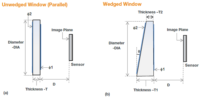
Schematic for dimensions of (a) Unwedged and (b) Wedged windows for the different cameras. (AR coating: inside diameter denoted by φ1, outside diameter denoted by φ2).
Table 2: Summary of the key dimensional data for each camera family
| 1 | 2 | 3 | Unwedged | Wedged | AR Coating (if present) | |||
| Diameter | Distance (Win to Sensor) | Thickness | Wedge Angle | Thickest edge | Thinnest edge | Diameter Inside | Diameter Outside | |
| Camera Model | DIA (mm) | D (mm) | T | θ° | T1 | T2 | AR – φ1(mm) | AR – φ2(mm) |
| iXon DU897 | 35 | 5.55 | 1.5 | 0.5 | 1.8 | 1.5 | 25.4 | 33 |
| iXon DU888 | 35 | 5.55 | 1.5 | 0.5 | 1.8 | 1.5 | 25.4 | 33 |
| iXon DU860 | 35 | 5.55 | 1.5 | 0.5 | 1.8 | 1.5 | 25.4 | 33 |
| iXon Ultra | 35 | 5.50 | 1.5 | 0.5 | 1.8 | 1.5 | 25.4 | 33 |
| iKon-M | 35 | 4.15 | 1.5 | 0.5 | 1.8 | 1.5 | 25.4 | 33 |
| Clara | 35 | 5.54 | 1.5 | 0.5 | 1.8 | 1.5 | 25.4 | 33 |
| iKon-L | 60 | 6.70 | 2.3 | No Wedged Option | 40 | 44 | ||
| Neo | 45 | 5.74 | 2.5 | 0.5 | 1.9 | 1.5 | 36 | 40 |
| Zyla | 45 | 4.91 | 2.5 | No Wedged Option | 36 | 40 | ||
| Newton | 45 | 7.14 | 1.5 | 0.5 | 2.6 | 2.2 | 36 | 40 |
| iDus | 45 | 6.64 | 1.5 | 0.5 | 2.6 | 2.2 | 36 | 40 |
| iVac | 45 | 4.11 | 1.5 | 0.5 | 2.6 | 2.2 | 36 | 40 |
| Newton-BRDD | 49.5 | 7.14 | 2.3 | 1.0 | 2.3 | 1.4 | 40 | 44 |
| iDus-BRDD | 49.5 | 7.14 | 2.3 | 1.0 | 2.3 | 1.4 | 40 | 44 |
| iDus-LDC-DD | 49.5 | 7.14 | 2.3 | 1.0 | 2.3 | 1.4 | 40 | 44 |
| iVac-LDC-BRDD | 49.5 | 7.14 | 2.3 | 1.0 | 2.3 | 1.4 | 40 | 44 |
| iKon-XL | 118 | 4.0 | 6.0 | No Wedged Option | 108 | 118 | ||
| Sona | 50 | 4.30 | 2.5 | No Wedged Option | 40 | 44 | ||
| Marana | 50 | 4.30 | 2.5 | No Wedged Option | 40 | 44 | ||
| Balor | 118 | 2.75 | 6.0 | No Wedged Option | 108 | 118 | ||
© Oxford Instruments 2024