Kymera 193i Spectrograph
View Product
 Part of the Oxford Instruments Group
Microspectroscopy covers a very wide range of spectroscopy modalities with the common character that the spectroscopic measurement is made on the microscopic scale. There are a number of approaches taken by researchers in configuring systems for such measurements, ranging from the acquisition of a fully integrated ‘push-button’ system that requires the minimum of training for the personnel using the equipment, to in-house purpose-built modular systems where the end-users build and integrate their own system from various individual components. This technical note outlines modular solutions in line with the latter approach for a range of different modalities.
The main components required to create an integrated system are illustrated in figure 1. Central to the integration and synchronization of the system components is software control. The main components include a microscope, spectrograph, detector, mechanical parts for coupling the spectrograph with the microscope, optical components for manipulation of the light along the optical paths and feet to match the optical heights between the microscope and spectrograph.
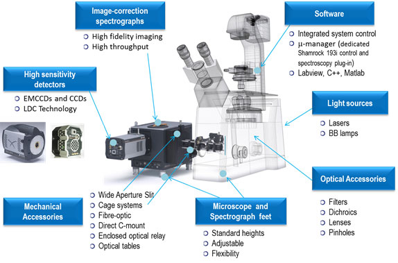
Figure 1: The main components of a modular microspectroscopy system
There is a diversity of areas where microspectroscopy is being applied. Depending on the sample to be analysed there may be one or several spectroscopy modalities used, as listed above. For example Raman spectroscopy is being used to characterise live cells, tissue, biomolecules as well as thin films of various materials such as graphene, carbon nanotubes and microfluidic samples. Optical Coherence Tomography (OCT) is used to investigate the retina of the eye and diagnose skin cancers. Within any given modality there is an ever increasing list of variants of the basic technique.
This technical note outlines some common configurations for coupling the spectroscopy system to various types of microscope – taking into account different spectroscopy modalities. A schematic layout is given for each configuration followed by a brief description. A list of possible (example) parts is then given for constructing such a system. For illustration purposes some specific parts from different suppliers are indicated but one should bear in mind that equivalent parts are available from a range of third-party companies and suppliers.
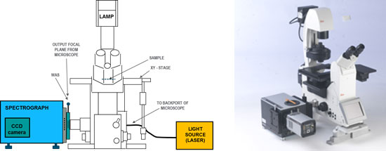
Figure 2: Schematic and picture of a spectrograph directly coupled to the side port of an inverted microscope.
The schematic shows an excitation light source coupled to the microscope using an optical fiber. However, the excitation may be coupled directly to a port – typically the back port – and may be a broad band source or a laser; the configuration will depend on the spectroscopy modality to be used in the experiment. This example could be used for a fluorescence or micro-luminescence application.
| Ref | Main Component | Notes |
| 1.1 | Spectrograph | Kymera 193i or 328i, Shamrock 500i, (incl shutter and filter wheel - recommended) |
| 1.2 | Detector – CCD camera | Range of CCD cameras but main choices are Newton EM DU971P-xx, iXon Ultra 888, Newton DU940P-xx |
| 1.3 | Microscope – Inverted with side port | Range of possibilities which include – Olympus IX71/81, Olympus IX83, Leica DMI 4000/6000B, Leica DMI 8, Nikon Eclipse Ti-E, Nikon TE-2000, Zeiss Axiovert-200, etc and custom built systems. |
| 1.4 | Wide Aperture Slit (WAS) | SR-ASZ-0086 for Kymera 193i/328i and Shamrock 500i/750 |
| 1.5 | C-mount adapter for slit housing | SR-ASM-0021 for all Shamrocks (attaches to WAS housing). |
| 1.6 | C-mount adapter on microscope output port | Sometimes this is not present and may need to be sourced – but most suppliers provide a c-mount port accessory. Thorlabs also provide port adapters [1,5]. |
| 1.7 | Feet for microscope | Optical height reference is 150 mm from top of optical table but custom feet are possible. Refer to Specification sheet [1] for some examples of feet available. |
| 1.8 | Feet for spectrograph | SR-ASM-0098 for Kymera 193i/328i, SR-ASM-0082 - SR500i/750 |
| 1.9 | Filters for microscope cube | Depends on experimental modality to be used and wavelength ranges of interest |
| 1.10 | Excitation light source | Depending on modality and configuration this may be a broadband light source or a laser, and may be coupled directly to a port or indirectly with an optical fiber. |
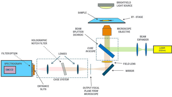
Figure 3: Schematic for a Raman setup with direct coupling of the spectrograph and microscope using a cage system.
The example illustrated in figure 3 looks at a Raman configuration specifically using a cage system to connect the spectrograph, via relay optics, to the side port of an inverted microscope. A 4f optical arrangement is used for the relay optics. Of course a similar arrangement could be used for a photoluminescence experiment with the notch filter removed from the cage and an appropriate choice of filters within the microscope. There are a large number of variations on this type of configuration but all essentially contain these main components. There is an example in the ‘Modular Solutions for Microspectroscopy’ specification sheet [1] which is similar but is based on having 30 mm diameter relay optics instead. A picture of such a cage arrangement between a microscope and the Kymera 193i is shown in figure 4. A schematic for building this example arrangement is shown in figure 5.
| Ref | Main Component | Notes |
| 2.1 | Spectrograph | Kymera 193i or 328i, SR500i (incl shutter and filter wheel) |
| 2.2 | Detector – CCD camera | Range of CCD cameras but main choices re Newton EM DU971P-xx, iXon Ultra 888 |
| 2.3 | Microscope – Inverted with side port | Range of possibilities which include – Olympus IX71/81, Olympus IX83, Leica DMI 4000/6000B, Leica DMI 8, Nikon Eclipse Ti-E, Nikon TE-2000, Zeiss Axiovert-200, etc and custom builds |
| 2.4 | Wide Aperture Slit (WAS) | SR-ASZ-0086 for Kymera 193i/328i and Shamrock 500i/750 |
| 2.5 | Shamrock cage adapter plate (30 mm cage system) | SR-ASM-0065 for all Shamrocks (attaches to WAS housing). |
| 2.6 | Cage adapter (30mm) to port of microscope | Depends on the microscope used: reference the specification sheet for ‘Modular Microspectroscopy Solutions’ [1] for possible options. Examples: For Zeiss Axiovert 200 side port – TR-ZSAV-CAGE-ADP, For Olympus IX81 side port – TR-OLIX-CAGE-ADP. |
| 2.7 | Cage rods (30 mm system) | Example based on parts from Thorlabs: Thorlabs rods: 12” – ER12 (x4), 3” – ER3 (x4), 1” – ER1 (x4), 0.5” –ER05 (x4) |
| 2.8 | Lenses – achromatic doublet VIS-NIR – 25 mm diameter | VIS-NIR, focal length 100 mm, diameter 25 mm. Example with optics from Edmund Optics: Edmund Optics part: NT49360-INK (x2) |
| 2.9 | XY lens holder -25 mm diameter | Mounted on cage rod system and holds lenses, Thorlabs cage part: XY lens holder (25 mm dia) – CXY1 (x2) |
| 2.10 | Turret mount to hold filter for 30 mm cage | Holds notch filter and allows for angular adjustment, Thorlabs cage part: Adjustable filter holder for 1” dia notch filter – KC45D (x1) |
| 2.11 | Notch filter | 1” diameter notch filter: choice depends on wavelength of the laser used. Some examples: From Andor - TH-0532-001 at 532 nm, TH-0633-001 at 633 nm, TH-0785-001 at 785 nm, Razor edge long pass filters may be used here as a variation. |
| 2.12 | Feet for microscope | Optical height reference is 150 mm from optical table but custom feet/heights are possible. Refer to specification sheet [1] for some examples of feet available. |
| 2.13 | Feet for spectrograph | SR-ASM-0098 for Kymera 193i/328i, SR-ASM-0082 for Shamrock 500i/750 |
| 2.14 | Filters for microscope cube | Depending on experimental configuration there may be a dichroic beam splitter in the cube or internal optical path of the microscope. For example this could be used to enable the excitation source to be coupled via another port (side or back). |
| 2.15 | Excitation light source | If the system is configured for Raman a laser will be used which may be coupled directly to a port or indirectly with an optical fiber. |
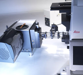
Figure 4: A picture illustrating the connection of a Kymera 193i to the side port of a microscope using a cage system.
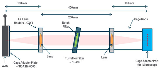
Figure 5: Schematic for the build of the cage system used in this configuration.
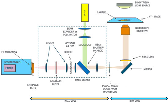
Figure 6: Schematic of setup for a Confocal Fluorescence Spectroscopy experiment. This depicts an inverted microscope with a cage system attached to its side port. The cage system on the left should be considered in plan-view – with a dichroic mirror being used to direct the laser excitation radiation on to the optical path of the microscope. The returning fluorescent signal passes through the dichroic, is then filtered through a pinhole, and finally is focused into the spectrograph.
This example configuration, schematic layout shown in figure 6, considers a setup for Confocal Fluorescence Spectroscopy based around a cage system, relay optics, a dichroic beam-splitter and a pinhole. In this example two arms are used in the cage system, one to introduce the excitation beam from a laser, and the other to deliver the fluorescent emission signal to the spectrograph. A 4f optical arrangement is used for the relay optics
Of course a similar arrangement could be used for a Raman Confocal Spectroscopy configuration with the use of an appropriate laser excitation, laser filter, and a notch or edge filter. Figure 7 shows a detailed schematic of the specific parts used in this configuration for the cage system.
| Ref | Main Component | Notes |
| 3.1 | Spectrograph | Kymera 193i or 328i, SR500i |
| 3.2 | Detector – CCD camera | Range of CCD cameras possible but main choices are Newton EM DU97xP-xx, Newton DU940P-xx, DU920P-xx, iDus 420A-xx |
| 3.3 | Microscope – Inverted with side port | Range of possibilities which include – Olympus IX71/81, Olympus IX83, Leica DMI 4000/6000B, Leica DMI 8, Nikon Eclipse Ti-E, Nikon TE-2000, Zeiss Axiovert-200, etc and custom builds |
| 3.4 | Wide Aperture Slit (WAS) –OPTIONAL (normally not required in this setup) | This is not necessary if pinhole is fixed. However, if it is desired to be able to move the pinhole in and out and have ability to capture relayed images of the sample with pinhole out then could be incorporated. However, not normally the case. If required: SR-ASZ-0086 for Kymera 193i/328i, SR-ASZ-0082 for Shamrock 500i/750 |
| 3.5 | Shamrock cage adapter plate (30 mm cage system) | SR-ASM-0065 for all Shamrocks (attaches to slit housing). |
| 3.6 | Cage adapter (30mm) to port of microscope | Depends on the microscope used: reference the specification sheet for ‘Modular Microspectroscopy Solutions’ [1] for possible options.Examples: For Zeiss Axiovert 200 side port – TR-ZSAV-CAGE-ADP, For Olympus IX81 side port – TR-OLIX-CAGE-ADP. |
| 3.7 | Cage rods (30 mm system) | Example based on parts from Thorlabs: Thorlabs rods: 12” – ER12 (x4), 3” – ER3 (x4), 1” – ER1 (x8), 0.5” –ER05 (x4), 4” –ER4 (x4), 6” - ER6 (x4). |
| 3.8 | Lenses – achromatic doublet for VIS-NIR – set 1 | Example optics: Region VIS-NIR, focal length 100 mm, 25 mm dia. (these correspond to lenses 1 and 2 in the figure 7). Example: Edmund Optics part no: NT49360-INK (x2) |
| 3.9 | Lenses – achromatic doublet VIS-NIR – set 2 | Example optics: Region VIS-NIR, focal length 45 mm, 25 mm dia. (these correspond to lenses 3 and 4 in figure 7). Example: Edmund Optics part no: NT49355-INK (x2) |
| 3.10 | XY lens holder -25 mm diameter | Thorlabs cage part: XY lens holder (25mm dia) – CXY1 (x2) (to mount lenses 1 and 2 on cage system). |
| 3.11 | Z lens holder (with lens tube) | Thorlabs cage part: Z translation mount – SM1Z (x2) (mounted with lens tubes SM1L05 pointing towards pinhole and holding lenses 3 and 4). |
| 3.12 | Lens Tubes | Thorlabs lens SM1 tubes: SM1L05 (x2) ( to mount to SM1Z and hold lenses 3 and 4). |
| 3.13 | Cage Translation stage – (30 mm) | Thorlabs cage part: Translation Stage - CT1 (x1), Also include part SM1RRan SM1 retaining ring. (to hold pinhole and allow for optimum focusing). |
| 3.14 | Pinhole in mount | Thorlabs mounted pinholes: PxxS (x1) where xx is 25 for 25?m, 10 for 10?m etc, e.g. P25S, P50S, P10S (mounted on translation stage CT1). |
| 3.15 | Quick release magnetic plate - OPTIONAL | As an alternative to a permanent holder for the pinhole on the cage a quick release part could be used to allow the pinhole to be taken in and out of the optical path easily – this would facilitate imaging (see earlier comment above): Thorlabs Quick-release magnetic plate: CP90F (x1) (mounted in place of parts pinhole translation stage CT1). |
| 3.16 | Cage cube (30 mm system) | Thorlabs cage cube: C6W (x1) ( contains through-holes for rods, holds the dichroic beamsplitter). |
| 3.17 | Cage cube platform (30 mm) | Thorlabs cage cube platform: B4C/M (x1) (platform mounted in cube to which is mounted the ‘filter’ holder for supporting the dichroic in place). |
| 3.18 | Cube cover plates (30 mm) | Thorlabs cage cube cover plates: B1C/M (x2) (blank off the unused sides of the cube). |
| 3.19 | ‘Filter’ holder for dichroic BS | Thorlabs cage cube filter holder: FFM1 (x1) (to hold the dichroic beam splitter in place). |
| 3.20 | Dichroic beam splitter (25 mm x 36 mm) | Dichroic beam splitter (mounted at 45°): Choice depends on excitation wavelength to be used but dimensions to be 25 mm (H) x 36 mm(W). Example: Thorlabs Dichroic mirrors/beam-splitters - DMLPxxxR where xxx denotes cut-off wavelength (e.g. DMLP505R for cut-off wavelength of 505 nm) |
| 3.21 | Cage mounting adapter (30 mm system) for support | To provide support for the cage system from the optical table (goes along with a post and post holder). Thorlabs cage mounting adapter: CP02B (x1) |
| 3.22 | Post holder + post (for support) | To provide support to the cage system. Thorlabs pedestal post holder: e.g. PH4E/M (x1) Thorlabs post for pedestal: e.g. TR75/M. Note choice of these will depend on height of optical axis required. |
| 3.23 | Beam expander or collimator | This will depend on how the excitation light source is delivered to the cage system, for example by free-space-coupling or via an optical fiber, and whether the beam is focused into the cage system or if it is collimated. There are a range of free standing beam expanders and collimators which can be used. Reference suppliers of various optical components [5]. One option is to construct a custom module with several lenses and cage system mechanical components. The example given here below is for light coupled from an excitation source through a fiber which is coupled to the cage system and is based on parts from Thorlabs. |
| 3.24 | Beam collimator example – fiber optic collimator | Thorlabs fiber optic collimator: F810SMA543 (x1) which is optimised in wavelength region of 543 nm and couples to an SMA fiber. (contains a lens and SMA connector – outputs a collimated beam). |
| 3.25 | Holder for collimator | Thorlabs fiber collimation package adapter: AD15F (x1) (holds collimator to cage mounting plate). |
| 3.26 | Cage plate for collimator | Thorlabs cage plate (SM1): CP02/M (x1) (for mounting collimator to cage system). |
| 3.27 | Feet for microscope | Optical height reference 150 mm from optical table surface but custom heights possible. Refer to specification sheet [1] for some examples of feet available. |
| 3.28 | Feet for spectrograph | SR-ASM-0098 for SR193i, SR-ASM-0080 for SR303i, SR-ASM-0082 for SR500i/750 |
| 3.29 | Filters – ‘excitation’ and ‘emission’ OPTIONAL (depending on system config.) | Excitation and emission filters may be added to the basic system if needed and these could be mounted on the cage system, in the cube of the microscope, or the filter wheel of the spectrograph. It is best to use standard 25.4 mm or 1” dia. filters. Example cage components which would mount these options: Thorlabs Cage plates (30 mm) : CP02/M (x2) (include an extra SM1RR retaining ring for each) or use QRC1A (quick release holder for 25.4 mm dia. filters) |
| 3.30 | Longpass filter | Isolates the fluorescence signal of interest. Depends on cut-off or wavelength edge required – some LP filters are available from Andor, as well as other suppliers. |
| 3.31 | Cage plate to hold long pass filter | Cage plate (or alternatively use the spectrograph filter wheel if one is installed.) Example from Thorlabs: QRC1A (quick release holder for 25.4 mm dia. filters) |
| 3.32 | Excitation Light source | Range of possibilities depending on wavelength needed. The example above illustrates the use of a laser. If the source is broadband then the light may be coupled either via free space or through a fiber but a narrow-band excitation filter will need to be added to the excitation input arm of the cage system before the sample (possibly in the cube or along the arm of the cage system). |
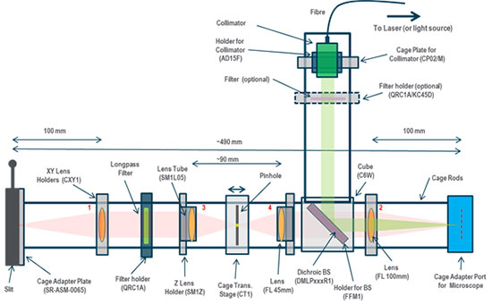
Figure 7: Schematic showing the details of the specific parts used in building of the cage system for this configuration.
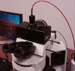
Figure 8: Configuring an upright microscope with optical fiber coupling.
Configurations which use the indirect coupling of optical fibers to the ports of microscopes are quite popular and relatively easy to configure. However, to ensure the best optimised system in terms of spatial resolution and light collection efficiency can prove challenging. This example demonstrates how an optical fiber can be coupled to the top port of a microscope. The fiber collects the sample signal and delivers it into the spectrograph. In some setups the core diameter of the fiber is used to determine and control the spatial resolution. Some variants in this approach use a pinhole in the optical path at the exit port (or elsewhere in the optical path where appropriate) – with a larger diameter single fiber or fiber bundle collecting the emerging light from the pinhole. The size of the pinhole determines the spatial resolution – with the magnification of the objective being taken into account of course. The pinhole acts as a confocal aperture and with the use of an XY motorised stage can be used to carry out 2D Confocal mapping of the sample.
| Ref | Main Component | Notes |
| 4.1 | Spectrograph | Kymera 193i or 328i, Shamrock 500i: (incl shutter and filter wheel - recommended.) |
| 4.2 | Detector – CCD camera | Range of CCD cameras but main choices are Newton EM DU97xP-xx, iDus 420/401/416 series, iXon Ultra 888, (note coupling flanges where needed) |
| 4.3 | Fiber adapter to spectrograph | Consider if SMA, FC or Ferrule fibers are to be used: depending on which type of fiber consider accessories - SR-ASM-8052, SR-ASM-8053, SR-ASM-8054, SR-ASM-8055, SR-ASM-8056, SR-ASM-8057, SR-ASM-8069. Reference the Shamrock specification sheets for details. |
| 4.4 | Optical fiber | Number of choices available but usually single core SMA or FC fibers used. Also core diameters sometimes chosen to define a confocal aperture hence small core diameters sometimes used. |
| 4.5 | Microscope – Upright and Inverted | Range of possibilities which include all of the main manufacturers as well as in-house custom systems. |
| 4.6 | Fiber adapter to exit port of microscope | Some examples based on Thorlabs parts: Microscope: Generic with c-mount port – consider using CMT1 (internal C-mount coupler), + SM1A39(external c-mount to SM1 thread) + SM1M05 (SM1 tube with internal thread), and either + SM1FC for FC fibers or SM1SMA for SMA fibers NOTE: Many microscopes come with c-mount adapters at their exit ports Microscope: Olympus IX71/81 & 73/83 (or BX) – consider using SM1A51(camera port adapter), + SM1L30 (1” diameter tube), + SM1V10 (adjustable focus adapter), and either + SM1FC for FC fibers or SM1SMA for SMA fibers Microscope: Leica DMI - consider using SM1A50 (camera port adapter), + SM1L20 (1” diameter tube), ), + SM1V10 (adjustable focus adapter), and either + SM1FC for FC fibers or SM1SMA for SMA fibers Microscope: Nikon Eclipse Ti-E – consider using SM1A44 (camera port adapter), + SM1L20 (1” diameter tube), ), + SM1V10 (adjustable focus adapter), and either + SM1FC for FC fibers or SM1SMA for SMA fibers Microscope: Zeiss Axioscope – consider using SM1A23 (camera port adapter), + SM1L20 (1” diameter tube), ), + SM1V10 (adjustable focus adapter), and either + SM1FC for FC fibers or SM1SMA for SMA fibers |
| 4.7 | Adapter to exit port incorporating pinhole option | Example based on Thorlabs and Andor parts: Assuming a standard c-mount exit port on microscope: SM1A10 – c-mount to SM1 tube adapter, attaches to c-mount exit port of scope. SM1L10 – SM1 lens tube (20 mm long) which carries pinhole and attaches to fiber holder - (includes retaining rings to hold optical component). CXY1 – XY adapter for SM1 tube system – allows for xy adjustment of collection fiber relative to pinhole. AD11F – adapter to carry fiber ferrule sleeve and attach it to the xy adapter. SR-ASM-0063 – sleeve ferrule for attaching SMA fiber to system. This has 11mm diameter. Alternative arrangement for a little more convenience: Use following parts in place of SM1L10: SM1M10 – SM1 lens tube with internal thread throughout.SM1T2 – to attach lens tube SM1M10 to the xy adapter CXY1 SM1RR – retaining ring for SM1 tube. |
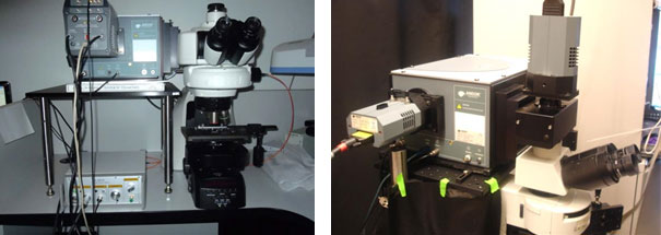
Figure 9: Examples where the spectrograph is coupled directly to the top port of upright microscopes.
It can be relatively straightforward to connect the spectrograph to the top port of an upright microscope, though this depends on the particular microscope involved and the space available. As illustrated in figure 9 the main component needed is a module with a turning mirror which directs the output signal from the top port into the entrance port of the spectrograph.
The main microscope manufacturers supply dual camera modules for the top port where a mirror at 45° to the main axis can be slid in and out of place depending on which optical path is to be used for the output of the microscope. Examples of such modules for dual port tubes are shown in figure 10 for Nikon (Y-QT) and Olympus (U-DPCAD) upright microscopes. The horizontal output from this module can either be coupled directly to the entrance slit housing of the spectrograph – space permitting – or to the relay optic which delivers the beam to the spectrograph sitting at some distance from the microscope. The spectrograph is supported on a table to match the required height of the output port of the microscope.
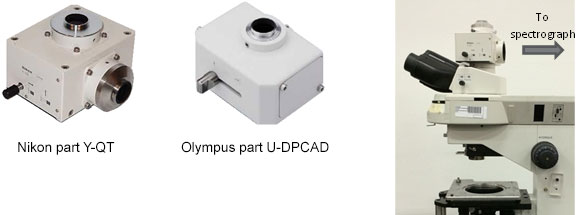
Figure 10: Examples of dual camera adapters for upright microscopes – Nikon part Y-QT and Olympus U-DPCAD.
There are a range of other options possible with infinity corrected microscopes for accessing the optical path at an exit port; these are best reviewed by consulting the technical details and manuals of the particular microscope concerned [7].
It is possible to set up a system with individual components with parts from one of the optical component suppliers. Below is an example of components from Thorlabs for attaching a turning mirror to the top port of an upright Nikon Eclipse microscope. Figure 11 illustrates how the parts in this example adaptation are put together.
| Ref | Main Component | Notes |
| 5.1 | Spectrograph (options) | Kymera 193i or 328i, Shamrock 500i, (incl shutter and filter wheel - recommended) |
| 5.2 | C-mount adapter plate for spectrograph slit housing | SR-ASM-0021 |
| 5.3 | Wide Aperture Slit (WAS) | SR-ASZ-0086 for Kymera 193i/328i and Shamrock 500i/750) |
| 5.4 | Relay optic (optional) | This can be used if there is not enough space to connect the spectrograph close to the port. SR-ASZ-0079 |
| 5.5 | Detector – CCD camera | Range of CCD cameras but main choices are Newton EM DU971P-xx, iXon Ultra 888 |
| 5.6 | Microscope – Upright with accessible top port | Range of possibilities from different manufacturers which include the example illustrated here – Nikon Eclipse E600 |
| 5.7 | Support platform/table for spectrograph | Need to choose one big enough for spectrograph and cage system. Examples of breadboards from Thorlabs: Thorlabs: MB4560/M - Aluminium Breadboard, 450 mm x 600 mm x 12.7 mm, M6 Threaded. Thorlabs: MB4545/M - Aluminium Breadboard 450 mm x 450 mm x 12.7mm M6 Threaded. Similar can be acquired from Newport, Edmund Optics, and Qioptiq among others [5]. |
| 5.8 | Support brackets for table | Support brackets for breadboard/table: Thorlabs parts: C1505/M (x4) - Metric Ø1.5" Mounting Post Bracket |
| 5.9 | Support posts | Support posts for breadboard/table: Example from Thorlabs: P350/M - Ø1.5" Mounting Post, Length=350 mm, M6 Taps x4 |
| 5.10 | Port adapter for top of microscope | This normally replaces the photomicrographic vertical tube which is usually standard on most trinocular systems. Thorlabs parts: SM1A58 - Port adapter |
| 5.11 | Cube | To hold turning mirror for redirection of main beam. Thorlabs parts: C4W - Cube for holding optics |
| 5.12 | Coupling tubes (30 mm system) | Tubes to connect port adapter to cube and cube to external optical path to spectrograph. Thorlabs parts (SM1 tubes): SM1T2 – between port adapter and cube, SM1T10 – between cube and spectrograph/relay optic. |
| 5.13 | c-mount adapter | To present a c-mount (male) connector towards the spectrograph or relay optic. Thorlabs part: SM1A9 - SM1 to c-mount adapter |
| 5.14 | Extension tube (30 mm system) | To connect the cube (and tube – SM1T10) to the c-mount adapter and allow for some adjustment to optimise focusing. Thorlabs parts (SM1 tubes) - options: 1) SM1L05 – adjustment tube (12.7 mm or 0.5” thread depth). 2) SM1L10 – adjustment tube ( 25.4 mm or 1” thread depth) |
| 5.15 | Blanking plate for cube | To close open port on side of cube. Thorlabs part: B1C-M |
| 5.16 | Blanking caps | To blank off un-used ports in cube. Thorlabs part: SM1CP2 (x2) |
| 5.17 | Kinematic platform for cube | To hold mirror mount and allow for optimisation of alignment. Thorlabs part: B4C/M – couples to one port of cube |
| 5.18 | Mount for mirror | To hold mirror inside cube. Thorlabs part: B5C (takes 1” diameter optics) |
| 5.19 | Mirror | To redirect output beam from microscope towards spectrograph. Thorlabs part: PF10-03-F01 (metal coated mirror) |
| 5.20 | Filters/Dichroics for microscope cube | Depending on experimental configuration, there may be a dichroic beam splitter in the microscope cube or internal optical path of the microscope. Consult the microscope manufacturer details for specifications [7]. |
| 5.21 | Excitation Light source | If the system is configured for Raman a laser will be used which may be coupled directly to another port or indirectly with an optical fiber. Often excitation light is delivered via the back port of the microscope. |
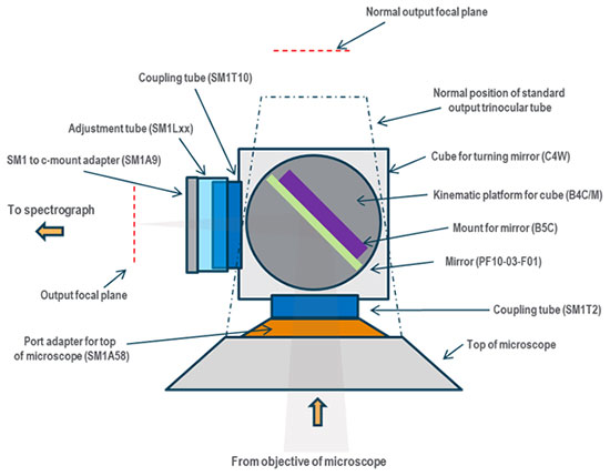
Figure 11: Schematic showing the details of the example chosen where specific Thorlabs parts are configured to adopt the top port of a Nikon Eclipse E600 microscope for direct coupling to a spectrograph.
A common configuration for microspectroscopy involves the coupling of the spectrograph using a cage system to the top port of an upright microscope. Figure 12 shows a picture of one such configuration used for Raman investigations on thin films [8]. Below in figure 13 is a schematic layout of a similar system for Raman mapping. Figure 14 illustrates how the parts for this example may be assembled.
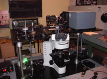
Figure 12: An example of a configuration with an upright microscope and coupling via a cage system [8].
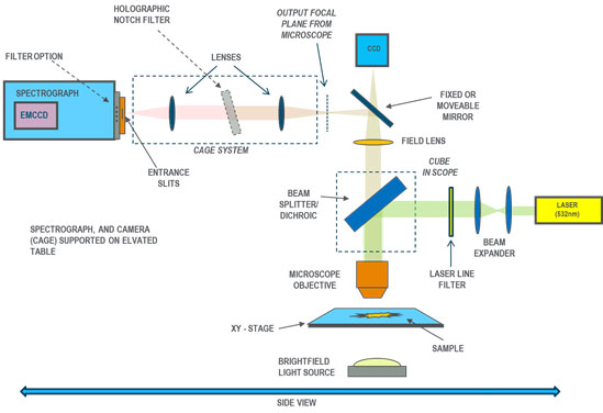
Figure 13: Schematic layout of system for Raman mapping on the microscopic scale based around an upright microscope. The spectrograph and camera are supported on an elevated table to match the height of the microscope port. A schematic layout showing the assembly of the parts used in this example configuration is shown in figure 14.
| Ref | Main Component | Notes |
| 6.1 | Spectrograph | Kymera 193i or 328i, Shamrock 500i, (incl shutter and filter wheel - recommended) |
| 6.2 | Detector – CCD camera | Range of CCD cameras but main choices typically are Newton EM DU971P-xx, iXon Ultra 888 |
| 6.3 | Microscope – Upright with accessible top port | Range of possibilities from different manufacturers which include Olympus BX51, Nikon Eclipse series, Zeiss Axio Scope series, Leica DM* series, etc, and various custom systems. |
| 6.4 | Support platform/table for spectrograph | Basically need to choose one big enough for spectrograph and cage system. Examples of breadboards from Thorlabs: Thorlabs: MB4560/M - Aluminium Breadboard, 450 mm x 600 mm x 12.7 mm, M6 Threaded. Thorlabs: MB4545/M - Aluminium Breadboard 450 mm x 450 mm x 12.7mm M6 Threaded. Similar can be acquired from Newport, Edmund Optics, Qioptiq among others [4]. |
| 6.5 | Support brackets for table | Support brackets for breadboard/table: Example from Thorlabs: C1505/M - Metric Ø1.5" Mounting Post Bracket x4 |
| 6.6 | Support posts | Support posts for breadboard/table: Example from Thorlabs: P350/M - Ø1.5" Mounting Post, Length=350 mm, M6 Taps x4 |
| 6.7 | Wide Aperture Slit (WAS) | SR-ASZ-0086 for Kymera 193i/328i and Shamrock 500i/750 |
| 6.8 | Shamrock cage adapter plate (30 mm cage system) | SR-ASM-0065 for all Shamrocks |
| 6.9 | Right angle turning mirror (incl. mount) | Right angled turning mirror and mount to pass beam from exit port into cage system. Example based on Thorlabs parts: KCB1C/M - Right angled kinematic cage mount, + PF10-03-F01 1” (25.4mm) diameter mirror – (mirror with UV enhanced aluminium coating) |
| 6.10 | Connector - c-mount exit to mirror holder | To connect the mirror mount to the exit port – exit port assumed to be standard c-mount: Example based on Thorlabs parts: SM1A10 – connects to c-mount of exit port and to turning mirror mount KCB1C/M |
| 6.11 | Cage rods (30 mm system) | Example based on parts from Thorlabs: Thorlabs rods: 12” – ER12 (x4) , 3” – ER3 (x4), 1” – ER1 (x4), 0.5” –ER05 (x4) |
| 6.12 | Lenses – relay optics | Achromatic lens doublet VIS-NIR – focal length 100 mm, diameter 25 mm. Example from Edmund Optics NT49360-INK (x2) |
| 6.13 | Lens holders | XY lens holders – for 25 mm diameter optics Thorlabs cage part: CXY1 (x2)- XY (25 mm dia. optic) |
| 6.14 | Turret mount to hold filter | Turret mount to hold notch or long-pass filter for 30 mm cage system. Thorlabs cage part: KC45D (x1) - adjustable filter holder for 1” dia notch filter. |
| 6.15 | Notch or Long Pass filter | 1” diameter notch filter: choice depends on wavelength of laser used. Examples from Andor: TH-0532-001 at 532 nm, TH-0633-001 at 633 nm, TH-0785-001 at 785 nm. Razor edge long pass filters may be used here as a variation. Filters available from a range of different manufacturers and suppliers. |
| 6.16 | Filters/Dichroics for microscope cube | Depending on experimental configuration there may be a dichroic beam splitter in the cube or internal optical path of the microscope – these are optional and usage will depend on particular experiment. |
| 6.17 | Excitation Light source | If the system is configured for Raman a laser will be used which may be coupled directly to a port or indirectly with an optical fiber. As per the picture of figure 12, and the example configuration 3 earlier – the laser may be brought in via a branch in the cage system. |
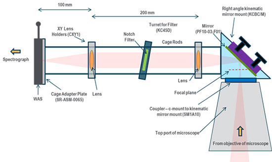
Figure 14: Schematic arrangement showing assembly of parts for configuration 6.
© Oxford Instruments 2024