Resources
 Part of the Oxford Instruments Group
Expand
Collapse
Part of the Oxford Instruments Group
The Zyla, Marana and iStar sCMOS Spectroscopy features are available on Zyla 4.2 and 5.5 Megapixel camera types with –S suffix and all iStar and Marana sCMOS as standard. A summary of the released feature set is shown below (Table 1).
NOTE: Spectroscopy features on Zyla are supported only with SDK3 & FPGA versions as below.
| FPGA | 4.2MP CL | 150806.0 or greater |
| 4.2MP USB3 | 150812.0 or greater | |
| 5.5MP CL | 150807.0 or greater | |
| 5.5MP USB3 | 150812.0 or greater | |
| SDK3 | Windows | 3.11.30001.0 or greater |
| Linux | 3.11.30002.0 or greater |
| Feature |
| Asymmetric binning |
| User definable bit depth |
| Multi-track mode |
| Automatic External Shutter Control (Zyla only) |
| User Configurable External Trigger Delay (Zyla only) |
Table 1 - Spectroscopy feature set
Asymmetric Binning
The sCMOS Spectroscopy feature set allows users to configure any combination of vertical and horizontal binning. This will allow users to avail of full vertical binning for their spectroscopy applications. For horizontal binning the user can select up to 36 horizontally binned pixels. An additional restriction in the horizontal direction means that a user cannot select a horizontal bin number which is greater than ¼ of the AOI width. The binning parameter space is described in table 2.
| AOI Height | AOI width | Maximum Vertical Binning | Maximum Horizontal Binning |
| 2160 | 2560 | 2160 | 36 |
| 2048 | 2048 | 2048 | 36 |
| 512 | 512 | 512 | 36 |
| 128 | 128 | 128 | 32 |
| H | W | H | Lower of: 36 or W/4 |
Table 2 - Table providing example binning range options for different AOI settings
SDK3 Feature Reference
It is typical for a user to configure their required binning options in conjunction with Area of Interest (AOI). Shown below is a list of all AOI features which include vertical and horizontal binning control. Please refer to section 4.6 of the SDK3 Manual for a more detailed description of how to set up AOIs and binning.
| Feature | Type | Description |
| AOIHBin | Integer | Configures the Horizontal Binning of the sensor area of interest. |
| AOIHeight | Integer | Configures the Height of the sensor area of interest in super-pixels. |
| AOILeft | Integer | Configures the left hand coordinate of the sensor area of interest in sensor pixels. |
| AOITop | Integer | Configures the top coordinate of the sensor area of interest in sensor pixels. |
| AOIVBin | Integer | Configures the Vertical Binning of the sensor area of interest. |
| AOIWidth | Integer | Configures the Width of the sensor area of interest in super-pixels. |
User Definable Bit Depth
Standard pixel encoding options on Zyla, Marana and iStar sCMOS are 12-bit (Low Noise) or 12-bit (High Well Capacity) and 16-bit (Low Noise & High Well Capacity). This limits the options for bit depth digitised on head and transmitted over the camera interface. In these configurations the bit depth is optimized to preserve dynamic range for 1x1 binning. However if a user for example chooses 2x2 binning this results in situations where the sum of the pixel count values exceed the maximum digital value transmitted. For example if a user is running in 16-bit mode in 1x1 binning, imaging at half well depth, then a given pixel will transmit 30,000 counts of data per pixel which is below the 16-bit digitization range. If they then select 2x2 binning then the binned superpixel will contain 120,000 counts of data. If the digitization is capped to 16-bit then this super pixel will be saturated at 16-bit (65,536 counts), this means that the dynamic range of the camera is not preserved.
The sCMOS Spectroscopy feature set allows the user to select any bit depth to be transmitted over the camera interface (up to 32-bits) independent of the SimplePreAmpGainControl selection. This allows the user to select any binning combination and still preserve the dynamic range of the camera.
SDK3 Feature Reference
The user can separately define the gain setting through SimplePreAmpGainControl and the transmitted bit depth via PixelEncoding.
| Feature | Type | Description |
| SimplePreAmpGainControl | Enumerated | Options
|
| PixelEncoding | Enumerated | Configures the format of data stream. Options
|
Multi-Track Mode
Multi-track mode allows creation of one or more individual acquisition tracks that can be defined (in rows) by the height and position of each track. In this way, the position of the tracks can be adjusted to match a light pattern produced on the sensor, for example by a fibre-optic bundle. Only the sections of the sCMOS image chip that are selected in Multi-track mode are transmitted across to the PC. All the selected tracks are transmitted as a single frame for each acquisition. Users can define up to 256 individual tracks of any height. Each track can be individually set up to have either 1x1 binning or fully vertically binned. Users cannot define the width of the tracks, whether individually or globally – the tracks width is always identical to the full width of the sensor. Figure 1 shows a schematic of the Multi-track mode configurations.
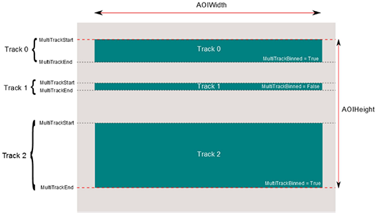
Figure 1 - Multi-track setup schematic
If should be noted that the AOI Height is not settable in Multi-track mode. Instead, the total AOI height and position will be determined by the start position of Track 0 and end position of track N-1 where N is the number of tracks.
SDK3 Feature Reference
| Feature | Type | Description |
| AOILayout | Enumerated | Options
|
| MultitrackCount | Integer | It is in the range 0-256. When set to 0, multitrack is disabled. |
| MultitrackSelector | Integer | Selects multitrack index. It is in the range 0-(MultitrackCount-1). |
| MultitrackBinned | Boolean | Configures whether the currently selected multitrack will be binned or not. Default state is set to true. |
| MultitrackStart | Integer | Configures the row at which the currently selected multitrack begins. |
| MultitrackEnd | Integer | Configures the row at which the currently selected multitrack ends. |
Automatic Shutter Output (Zyla and Marana only)
If Automatic shutter control is selected the Aux_Out_2 TTL signal will go high for the duration of an acquisition or acquisition sequence. The user can also define a Shutter Transfer Time which delays the time between the Aux_Out_2 signal going high and the start of the 1st acquisition in an acquisition sequence. Figure 2 shows a timing diagram for Automatic Shutter Output. Table 3 shows the available Shutter Transfer Time range.
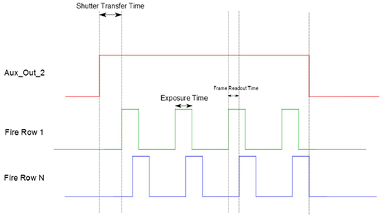
Figure 2 - Timing diagram describing the Aux_Out_2 signal output when configured in Automatic Shutter Output mode for a kinetic sequence of 4 frames. Timing diagram also illustrates the user configurable shutter transfer time.
| Sensor Readout Rate | Available Shutter Transfer Time Range |
| 540 MHz | 0 - 7.95 seconds |
| 200 MHz | 0 - 20.79 seconds |
Table 3 - Shutter Transfer Time range depending on Sensor Readout Rate
SDK3 Feature Reference
| Feature | Type | Description |
| AuxOutSourceTwo | Enumerated | AuxOutSourceTwo is a configurable output available to the user on the D-type. Options
|
| ShutterOutputMode | Enumerated | Controls the mode the external trigger will run in. External Shutter signal can either be set to high (open) or low (closed). ShutterOutputMode can be triggered by setting AuxOutSourceTwo to ExternalShutterControl. Options
|
| ShutterTransferTime | Float | Defines the delay, in seconds, between the shutter signal going high and the start of exposure of frame 1 in a kinetic series. |
User Configurable External Trigger Delay (Zyla and Marana only)
This feature allows the user, when using external or software trigger modes, to define a delay time between the camera receiving an external trigger and the acquisition start. Table 4 shows a summary of the parameter space for this feature. Note that “Cycle Time” refers to the standard cycle time as can be found in the respective Hardware Guides.
| Trigger Mode | External Trigger Delay Available | Sensor Readout Rate | Available Trigger Delay Range (Delay) | Min Cycle Time |
| Internal | No | 540 MHz | N/A | Cycle Time |
| 200 MHz | N/A | Cycle Time | ||
| External | Yes | 540 MHz | 0 - 7.95 seconds | Delay + Cycle Time |
| 200 MHz | 0 - 20.79 seconds | Delay + Cycle Time | ||
| External Start | Yes | 540 MHz | 0 - 7.95 seconds | Cycle Time |
| 200 MHz | 0 - 20.79 seconds | Cycle Time | ||
| Software | Yes | 540 MHz | 0 - 7.95 seconds | Delay + Cycle Time |
| 200 MHz | 0 - 20.79 seconds | Delay + Cycle Time | ||
| External Exposure | No | 540 MHz | N/A | Cycle Time |
| 200 MHz | N/A | Cycle Time |
Table 4 - User Configurable External Trigger Delay parameter space
The granularity of External Trigger Delay control is set to 1 us although it should be noted the jitter between external trigger and exposure start is up to one row readout time. The values of row readout times for different scan speed can be found in the respective Hardware Guides.
SDK3 Feature Reference
| Feature | Type | Description |
| ExternalTriggerDelay | Floating Point | Configures the delay, in seconds, between external/SW trigger and exposure start |
© Oxford Instruments 2024