Resources
 Part of the Oxford Instruments Group
Expand
Collapse
Part of the Oxford Instruments Group
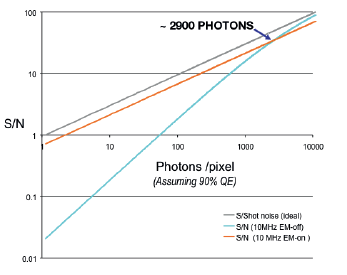
Figure 1 - EM gain-ON vs EM-gain-OFF signal to noise plots for back-illuminated iXon EMCCDs at 10 MHz readout speed - applies to 897, 860 and 888 models.
It is often questioned whether or not to use EMCCD gain or whether to use EM or conventional CCD amplifiers (model dependent). The answer usually depends both on required frame rate and on light levels. Plots of Signal to Noise ratio vs Signal Intensity can be instructive in making such decisions. Here we introduce the concept of Signal to Noise in EMCCDs and discuss such plots.
Part 1 - Understanding Noise Sources in EMCCDs
Read Noise
Read Noise in many instances can be considered the true CCD detection limit, particularly the case in fast frame rate experiments because, (a) short exposures combined with low darkcurrent make the darkcurrent contribution negligible and (b) faster pixel readout rates, such as 5 MHz and higher, result in significantly higher readout noise. The fundamental advantage of EMCCD technology is that gains are sufficient to effectively eliminate readout noise, therefore eliminating the detection limit.
Multiplicative Noise
This noise source is only present in signal amplifying technologies and is a measure of the uncertainty inherent to the signal multiplying process. For example, during each transfer of electrons from element to element along the gain register of the EMCCD, there exists only a small probability that the process of impact ionization will produce an extra electron during that step. This happens to be a small probability but when executed over more than 590 steps, very large potential overall EM gains result. However, the downside to this process results from the probabilities. Due to this, there is a statistical variation in the overall number of electrons generated from an initial charge packet by the gain register. This uncertainty is quantified by a parameter called "Noise Factor" and detailed theoretical and measured analysis has placed this Noise Factor at a value of √2 (or 1.41) for EMCCD technology. This is an additional form of noise that must be taken into account when calculating Signal/Noise for these detectors. Note that this noise source is significantly greater from the MCP of ICCDs than from the gain register of the EMCCD. ICCDs have noise factors typically ranging from 1.5 to >2.
However, one way to better understand the effects of this noise source is in terms of an addition to the shot noise of the system. Extra multiplicative noise has the same form as shot noise in that each noise type results in an increase in the variation of number of electrons that are read out of a CCD (under constant uniform illumination). Indeed multiplicative noise can be thought to contribute directly to the overall shot noise, in that one should multiply the Shot Noise by the Noise Factor when calculating overall noise.
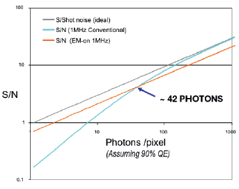
Figure 2 - EM gain-ON vs Conventional Amplifier signal to noise plots for back-illuminated iXon EMCCDs at 1 MHz readout speed – applies to 897 and 888 models.
Simply put, multiplicative noise does not in any way reduce the average signal intensity or reduce the number of photons that are detected, it simply increases the degree of variation of the signal around the mean value, in addition to the variation that already exists from the shot noise (variation from pixel to pixel or from frame to frame).
Dark Current
Due to the effective cooling inherent to Andor's cameras, dark current is minimized, and may often be considered practically negligible. The extent of contribution is dependent on exposure time, since the darkcurrent is quoted in electrons/pixel/sec. It is particularly important to eliminate darkcurrent with EMCCD technology as even single thermally generated electrons in the silicon will be amplified in the gain register just as a single photoelectron, and will appear in the final signal as a single noise spike. Fortunately, for fast frame rate experiments combined with iXon very low darkcurrent, this noise source may be ignored.
Spurious Noise
Spurious Noise appears in the form of Clock Induced Charge (CIC) in EMCCD technology. CIC is independent of exposure time and generally single electron events generated during charge shift (EBI is the form of spurious noise in ICCDs and is exposure dependent). CIC is generated in every CCD but is normally buried in the readout noise. In the EMCCD however, these single electrons are amplified by the gain register just as a single photoelectron would be. In the EMCCD, CIC can in some ways be considered the true limit of detection, in that at the single photon detection level, a single photon spike will be indistinguishable from a CIC spike. Andor has specialized electronics however, that enable this source of noise to be minimized. In practical terms, ultra-weak signals of the single photon nature would be distinguishable from CIC spikes in that one could generally expect to see 'groupings' of photon spikes from adjacent pixels, even from diffraction limited single molecule emissions.
Simplified consideration of EMCCD noise
From the above list it is apparent that in most uses of Andor’s iXon cameras, since read noise and darkcurrent can be virtually eliminated (i.e. the noise sources that would define the detection limit have been rendered effectively negligible), the principal sources of noise that must be considered are shot noise, noise factor (multiplicative noise) and spurious noise.
It is easy to combine shot noise and multiplicative noise in an overall noise equation, using:
Overall Noise = Shot Noise x 1.41 Shot Noise can be determined if the average signal is measured in electrons - by measuring in electrons, the calculation is independent of the sensor’s QE - i.e. the photons have already been converted to photoelectrons so the QE corrected signal is being measured. If the average signal in photons is already known (e.g. estimated from other measurements with PMTs), the shot noise can be corrected for sensor QE at that wavelength: 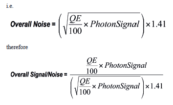
Since spurious noise is very different in nature to shot noise, it is best to consider spurious noise separately. Each EMCCD will have a measured figure for the levels of CIC spikes to be expected during a readout. This will present a figure for the average number of random spurious single electron spikes that will appear within the image. If the measured signal is at the very low photon level (one or two electrons per pixel), this noise source will be more significant. If the signal is slightly more intense than this, it may become less of an issue, and may even be filtered out. Note that often, the minimal amount of spurious noise remaining from the iXon is minor compared to the level of background photons in the image.
Part 2: Signal to Noise Plots
EM gain ON vs EM gain OFF (faster speeds) Figure 1 shows Signal to Noise plots derived from the specs of the back-illuminated iXon EMCCDs, read out at 10 MHz (for fastest frame rates). A photon wavelength at which the QE of the sensor is 90% is assumed. Such plots are very useful to gauge the signal intensity at which it becomes appropriate to use EM gain to increase S/N. It is clear that at 10 MHz readout, one needs to encounter relatively intense signals of > 2900 photons / pixel before it becomes advantageous to operate with EM gain off. Note that the ‘ideal’ curve represents a pure Signal to Shot Noise and is shown for reference – if the detector had no sources of noise, this is what the curve would appear like. Even with EM gain turned on we encounter uniformly lower signal to noise than the ideal curve. This is due to the influence of EM Multiplicative Noise, which has the effect of increasing the shot noise by a factor of √2 (~1.41). Note, Multiplicative Noise (Noise Factor) is generally higher for ICCDs.
EM vs Conventional Amplifier (slower speeds)
Figure 2 shows Signal to Noise plots derived from the specs of the back-illuminated iXon EMCCDs at 1 MHz (slower frame rate operation), read out either with EM gain ON or alternatively through the Conventional amplifier (i.e. standard CCD operation). Again, a photon wavelength at which the QE of the sensor is 90% is assumed. Specifically this figure applies to 897 and 888 models for which this choice of amplifier is available.
Under slower speed operations, when one has the choice to read out as a 'conventional CCD', it can often be advantageous to do so in terms of achieving better signal to noise. Indeed the plots show that the cross-over point is at ~ 42 photons / pixel, below which it is advised still to readout through the EM amplifier with gain applied.
© Oxford Instruments 2024