Resources
 Part of the Oxford Instruments Group
Expand
Collapse
Part of the Oxford Instruments Group
Sensitivity is a key performance feature of any detection system. When assessing the sensitivity of any CCD sensor it is the achievable Signal-to-Noise Ratio (SNR) which is of key importance. This encapsulates the capacity to have the signal stand out from the surrounding noise.
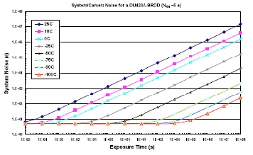
Figure 1: The detection limit as a function of exposure time for single pixel (imaging mode) which are read out at 33 kHz with readout noise of 4.6 electrons.
The approach to ensure the best possible SNR ratio is to a) develop a sensor with the highest possible quantum efficiency and b) reduce the various sources of noise to a minimum.
SEE ALSO: Signal to Noise Ratio & Noise Exposure Calculator
Quantum Efficiency (QE) is related to the ability of the sensor to respond to the incoming photon signal and the conversion of it to a measurable electron signal. Clearly the greater the number of photoelectrons produced for a given photon signal the higher the QE. QE is usually expressed as a probability – typically given in percentage format – where for example a QE of 0.6 or 60% indicates a 60% chance that a photoelectron will be released for each incident photon. QE is a wavelength or photon energy dependent function, and a sensor is generally chosen which has the highest QE in the wavelength region of interest. Various means have been employed to improve the quantum efficiency of CCD sensors. These include:
The next key challenge is reducing the overall noise to its minimum (the latter is often referred to as the noise floor). Shot noise within the photon generated (electronic) signal (S) is an intrinsic contribution to the overall noise and is related to fundamental quantum physics; it will always be part of any signal. If the number of photons in the incident signal is denoted by P and the quantum efficiency by QE, the photoelectron signal generated will be given by S = (QE.P).
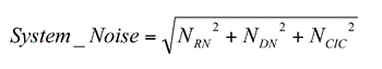
Next to consider is the system or camera noise which has three main contributors: the dark current (DC) of the sensor, spurious charge such as clock induced charge (CIC), and the readout noise from the output electronics (pre-amp and A/D node). The sources of noise and the means of dealing with them are summarized below:
Usually a high performance camera is operated at certain temperatures and clocking speeds such that the detection limit is determined by the readout noise. The various sources of noise may be added in quadrature to give the overall system or camera noise which may be expressed as:
The system noise characteristics for a typical iDus – BRDD CCD camera are shown in figure 1. Clearly the dark noise will rise with increase in exposure times such that for long exposures the overall system noise (and consequently the detection limit) will become dominated by the dark noise contribution. With cooling, the dark noise contribution is reduced significantly and with sufficient cooling can be reduced to an insignificant level. This shows up as the plateau region where the system noise is now readout-noise limited.
The advantage of cooling is evident when extremely long exposure times (>10’s, if not 100’s of seconds) are required in a given experiment. However, if short exposure times are being used, then it is clear that there is little benefit in using ultra deep cooling. As an illustration, consider exposure times less than 1000 seconds (a long exposure time).
There is little or no advantage cooling the sensor below -75ºC, where the system is operating on the low plateau corresponding to the read out noise limited regime. Similarly, if exposures less than 10s are being used, there is little or no benefit to be gained by cooling below -50ºC. When the temperature dependence of the QE is considered then one has to be careful when choosing the best operating point or temperature for optimum performance particularly if working in the NIR region.
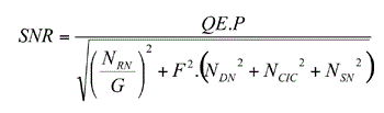
The overall signal to noise (SNR) for a given CCD system may be expressed in the form:
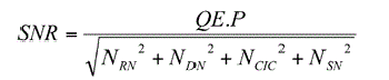
This function enables the performance of any conventional CCD to be assessed given the values for the key parameters – usually contained in the specification or performance sheets.
A number of points worth noting are:
Advanced detectors have been developed to extend sensitivity to the level of detecting a single photon. These systems amplify the initially detected signal using a multiplication process leading to an enhanced S/N at the read out of the CCD. The two main technologies are:
The degree by which a basic signal is amplified or multiplied is referred to as the gain factor. This can be selected through the software and leads to alteration of the voltages across the MCP in the case of the ICCD and the clocking voltages applied in the EM read out register of the EMCCD.
When an EMCCD or ICCD is being used an additional source of noise must be taken into account which is associated with the amplification process itself; this variation is intrinsic to any multiplication process. This is quantified by what is termed the Noise Factor (F). For EMCCD cameras the noise factor is v2 or ~1.41. The noise factor in ICCDs depends on the type and quality of intensifier tube used: these can have values from ~1.6 to ~3.5. Taking the noise factor (F) and the actual or real gain (G) into account, the total noise for systems offering gain may be expressed as:
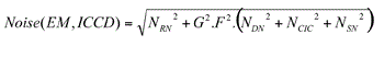
The SNR ratio for an EMCCD or ICCD may be written as:
When high performance systems are operated in a deep cooled lownoise regime, where dark and spurious noise are negligible compared with the read out noise, this expression for the SNR may be simplified to:
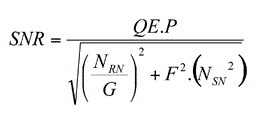
It can be seen here that by increasing the gain G, the term involving the read-out noise, NRN, becomes insignificant compared with the intrinsic shot noise of the signal, leading to ultra-sensitive detection capability. EMCCD and ICCD systems operated with appropriate configurations with sufficiently high gain can be used for single photon counting type experiments.
Explore our related assets below...
© Oxford Instruments 2024