iStar 334T CCD
View Product
 Part of the Oxford Instruments Group
This note describes the function of the Andor iStar DH734-18U-63 intensified CCD camera (ICCD) as a detector in a spectroscopic system to perform Thomson scattering (TS). The laser scattering technique was applied to a Surfatron plasma. The typical parameters are an absorbed power of 50 W in an argon gas environment of 20 mbar. That leads typically to an electron density (ne ) of 5·1019 m-3 and an electron temperature (Te) of 1.1 eV.
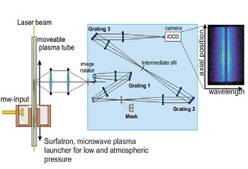
Figure 1: a) Setup for Thomson scattering,
Thomson scattering is the scattering of photons by free electrons in an ionized gas. Since the number density of scattered photons and their spectral distribution is directly related to important plasma properties such as ne and Te, it is one of the most prominent techniques in plasma diagnostics. However, the incoming laser beam interacts with bound electrons as well, which generates Rayleigh or Raman scattered light. During the detection we have to discriminate these photons from the Thomson scattered one. Combined with the collection of false stray light created by the reflection of the laser beam or side-beam on the vacuum vessel makes TS a very demanding technique. Moreover, TS is an active diagnostic method, thus the influence of the diagnostical laser beam on the plasma itself has to be monitored carefully. In spite of these demands, TS has the unique feature that it does not depend on assumptions about the plasma state of equilibrium. While directly probing ne and Te, we achieve accuracy better 5%.
The TS experiments in our study have been performed on a Surfatron induced plasma1. This adds another experimental difficulty. The plasma is situated inside a narrow quartz tube, which increases the amount of stray light drastically. Moreover, the TS signal has typically a very low intensity compared to other scattering and stray mechanisms. The Thomson cross section is s = 6.7·10-29 m-2, which implies that for a typical plasma only a fraction of 10-15 of the incoming laser photons reaches the detection system. To overcome that, a triple grating spectrograph (TGS)2 equipped with the Andor iStar ICCD camera is used. With this setup we achieve low detection limits and high stray light rejection.
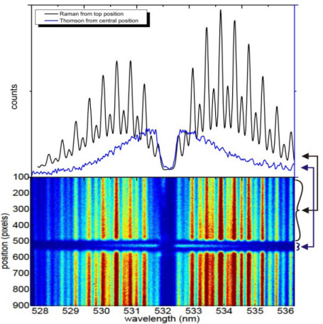
Figure 1b) typical results of laser scattering on atmospheric pressure plasma
Figure 1a schematically shows the design of the TGS. The first two gratings and a physical mask form a notch filter in order to block the central laser wavelength, while the third spectrometer resolves the actual spectral information. The latter is recorded onto the camera. For typical Surfatron plasma conditions the photons are scattered incoherently, meaning that the electrons respond independently to the laser E-field.
While the horizontal direction of the ICCD collects the spectral information, the second dimension of the camera is used to obtain spatial resolved measurements. The CCD sensor in the iStar has 1024 x 1024 x 13 µm pixels. In combination with the optical setup this leads to a spatial resolution of about 50 µm, which is a very advantageous feature to study the spatial distribution of the plasma. Thus we are capable to determine the plasma properties with one frame in high spatial and temporal precision2. The camera according to specifications has a jitter below 0.1 ns. However, the jitter in our system is determined by the laser and is below 5 ns. Moreover, the linearity of the camera allows using the whole dynamic intensity range.
As mentioned above the plasma source is a Surfatron. The microwaves are coupled into the plasma by means of a launcher that is situated around a quartz tube. For low pressure applications a controlled pressure can be set and for atmospheric conditions the tube is left open. The launcher cavity creates surface waves that form a spatially extended plasma column3. The whole plasma setup is moveable in axial and radial direction. For the TS a frequency doubled Nd:YAG laser at 532 nm with an energy of 0.1 J at a repetition frequency of 10 Hz is aligned along the tube axis. In that way the complete diagnostic is stable in space and in principle does not have to be calibrated while the plasma can be moved in order to probe the complete plasma volume. The recording ICCD camera is triggered by the laser so that the plasma is only observed in the short timeframe of the laser pulse. This implies that almost no plasma light is recorded.
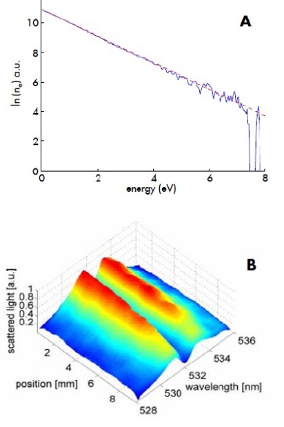
Figure 2: a) The EEDF of the Surfatron plasma obtained by Thomson scattering with the ICCD camera system. Electrons with energies above 7.5 eV cannot be detected. b) 3-dimensional presentation of the Thomson scattered light from the end of a discharge column of a Surfatron low pressure plasma.
After a careful alignment procedure we obtain images as in figure 1b. It shows colour-coded the scattered photon intensity as a function of the wavelength (abscissa) and the axial position (ordinate). The central dip in intensity can be clearly seen at the laser wavelength 532 nm, due to the filtering function of the TGS. In the top and bottom part of the picture Raman scattered photons on surrounding air can be seen, since that image was recorded in atmospheric conditions. The Raman spectrum (see in upper half of 1b) is used for the absolute intensity calibration of the image4. In the vertical central region one can see a different intensity distribution, namely that of Thomson scattered photons. The total intensity of that signal is directly proportional to ne. The distribution is a Gaussian shape which can be seen also in the upper half of figure 1b. That shape reflects the Doppler broadening of the electrons. Thus a 1-dimensional velocity distribution is obtained. We can plot the TS signal in a semi-log scale as a function of the wavelength-shift squared and make a linear fit. An example of that is shown in figure 2a. If this fitting is successful, we can safely assume to observe a Maxwellian distribution where the slope (or the Gaussian width in non-log plot) determines Te in the following way:
Te = mec2/8kBsin2(f/2) (??1/e/?i)2
And in our case
(f = p/2, ?i = 532 nm): Te = 5238 ??1/e 2 K.
The example of the energy distribution function obtained by the TS in figure 2a stresses how important the overall sensitivity of the whole setup is. The better the sensitivity, the more high energetic electrons are detected. The noise upon the linear fit for the first 6 eV is very small. That states that the noise created by dark current and by stray light is very small. On the other hand the overall detection limit is important. We detect ne values down to 1018 m-3 spatially resolved. The detection limit is strongly influenced by the stray light rejection capabilities of the TGS and the noise of the camera. The subtraction procedure of a background allows suppressing the stray light. However, that is greatly enhanced by the use of a low noise camera.
The spatial structure of the end of the discharge as shown in figure 2b, as well as the temporal behaviour of the plasma can be revealed. A sophisticated setup for stray light and laser light rejection enables us to record an image of the discharge showing spatial and spectral information of the Thomson scattered photons at once 3,5. Since the laser system and the optical detection branch are separated, we can easily investigate various small scale plasma sources and study them spatially resolved. Especially interesting are cool atmospheric pressure plasmas where the good spatial resolution is of particular interest, since the gradients of these plasmas can be in the order of 0.1 mm.
1) M. Moisan, Z. Zakrzewski, R. Pantel, The theory and characteristics of an efficient surface wave launcher (surfatron) producing long plasma columns, J. Phys. D Appl. Phys. 12 (1979) 219–237.
2) M.J. van de Sande, Laser scattering on low temperature plasmas—high resolution and stray light rejection, PhD Thesis Eindhoven University of Technology (2008), Eindhoven
3) H. Schlüter, A. Shivarova, Travelling-wave-sustained discharges, Phys. Rep. 443 (2007) 121–255.
4) N. de Vries, J.M. Palomares, W.J. van Harskamp, E. Iordanova, G.M.W. Kroesen, J.J.A.M. van der Mullen, Thomson scattering measurements on a low pressure surface wave sustained plasma in argon, J. Phys. D Appl. Phys. 41 (2008) 105209.
5) J.M. Palomares, E. Iordanova, E.M. van Veldhuizen, L. Baede, A. Gamero, A. Sola, J.J.A.M. van der Mullen, Thomson scattering on argon surfatron plasmas at intermediate pressures: Axial profiles of the electron temperature and electron density, Spectrochim Acta B 65 (2010) 225–233.
Prof. J.J.A.M van der Mullen
Elementary Processes in Gas Discharges
Department of Applied Physics
Eindhoven University of Technology
5600 MB Eindhoven
The Netherlands
Phone: +31 (40) 247-4043
Email: j.j.a.m.v.d.mullen@tue.nl
Web: http://www.tue.nl/en/university/departments/applied-physics/
© Oxford Instruments 2024